SiC Power Module Reliability: Wolfspeed’s Power Cycling and Lifetime Modeling Approach


Article
Introduction
The rapid adoption of Silicon Carbide (SiC) power devices across automotive, renewable energy, industrial e-mobility, and aerospace markets has redefined system requirements. Traditional qualifications are no longer sufficient. Customers now demand durability, ensuring that systems can operate continuously in harsh environments for decades with minimal downtime.
The electrification of transportation, renewable energy integration, and industrial automation place unprecedented demands on power semiconductor modules. Reliability, durability, and lifetime prediction are paramount, particularly in automotive and industrial applications where failure is not an option. This paper outlines Wolfspeed’s approach to addressing the challenges of power cycling in SiC power modules, exploring failure modes, testing methodologies, lifetime modeling, and the company’s portfolio of high-performance modules designed for long service life under demanding conditions.
Filling the Gap Between Reliability and Durability
Power electronics standards and qualification are covering many possible real-world cases but not all. A module may pass all standard reliability tests yet fail prematurely in the field due to mission-specific stresses not captured in conventional qualification protocols.
For example, HTRB (High Temperature Reverse Bias test) is used to test the device in high temperature conditions, but over the time other tests more stressful have been added by the regulatory body. This led to the introduction of HV-H3TRB, used for testing the device in high temperature, high humidity and high voltage conditions at the same time.
This gap between laboratory reliability and field durability drives the need for more sophisticated testing methodologies, particularly power cycling analysis, which has emerged as one of the most relevant indicators of system lifetime in real-world applications.
When we talk about power cycling with the ultimate goal of creating a life model, there are no pass or fail number of cycles required. This means devices are tested in different conditions until the failure, but a product with very small number of cycles to failure is not tested differently from a very high number of cycles to failure.
Read this whitepaper to learn about Wolfspeed’s approach to reliability addressing a new set of performance expectations for system durability.
Fundamentals of Power Cycling
Temperature variations induce dimensional changes in material – typically expansion during heating and contraction during cooling. The magnitude of this dimensional change is material-specific and characterized by the coefficient of thermal expansion (CTE).
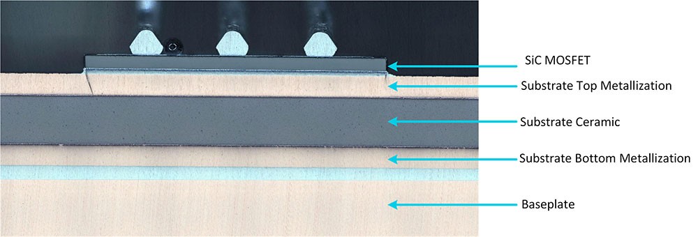
For power modules this becomes particularly critical because the substrate assembly consists of multiple dissimilar materials bonded together in a layered configuration, each responding differently to thermal cycling (Figure 1).
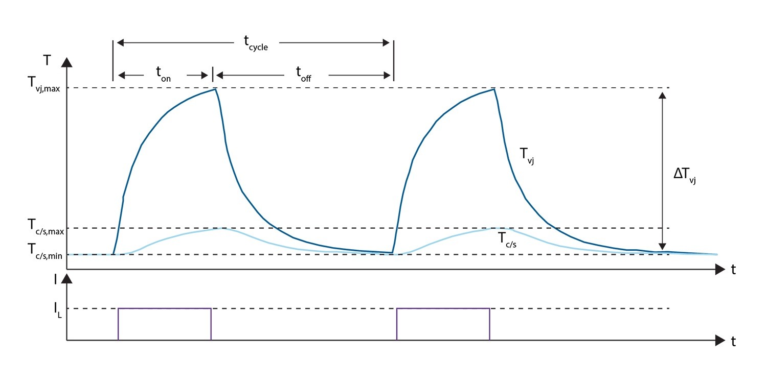
Power cycling (PC) testing represents the most suitable methodology for assessing SiC module durability under realistic thermal stress conditions. The fundamental principle involves subjecting power modules to repetitive current pulses (Figure 2) that generate controlled thermal swings within the device structure, mimicking the heating and cooling cycles experienced during actual operation.
The testing process centers on three critical stress parameters that, together, contribute to determining the device’s lifetime. The thermal swing (ΔTj) represents the temperature difference between the junction's peak operating temperature and its cooling baseline.
Maximum junction temperature (Tj,max) defines the absolute peak temperature reached during each cycle, influencing both the magnitude of thermal expansion and the activation energy of degradation mechanisms. Pulse duration (ton) determines how long the device remains at elevated temperature, affecting heat penetration depth through the substrate layers, and the extent of thermal equilibrium reached within the package structure.
Power cycling characterization requires running samples to end-of-life across various operating conditions, specifically different Tj,max, ΔTj, and ton. By testing multiple units at each condition set, we can extract the relationship between these parameters and cycle lifetime, which forms the basis for constructing a predictive life model.
The pass/fail criteria Wolfspeed adopts for PC testing align with the AQG324 automotive standard. Two primary failure modes are monitored:
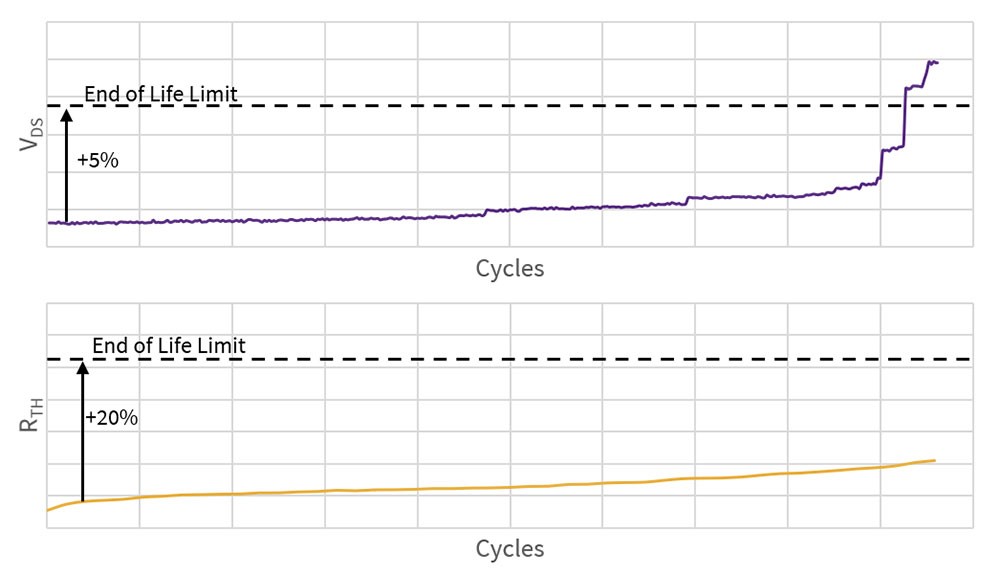
- The first criterion detects a +5% rise in VDS, which represents the voltage needed to maintain load current (IL) throughout the power pulse. This metric specifically identifies power cycling failures that can be attributed to die top-side interconnect, die detachment or any other type of electrical contact failure, which typically manifest as abrupt spikes in VDS.
- The second criterion tracks a +20% increase in thermal resistance (RTH). The system calculates RTH at every cycle by measuring the die's thermal response through the body diode's forward voltage during the off-time period . When RTH increases, it represents a degradation in the thermal dissipation path within the power module's layered structure, compromising thermal conductivity from the die to the heatsink.
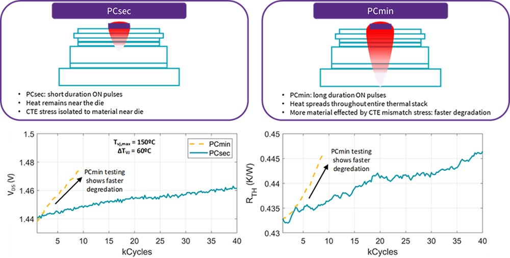
Two distinct testing profiles have emerged as industry standards. PCsec testing employs pulse durations of a few seconds, concentrating thermal stress near the die and primarily targeting die top-side interconnect and die attach interfaces. PCmin testing uses ton pulses >15 seconds to minutes, allowing deeper heat penetration through substrate layers and stressing solder joints and baseplate or package attachments. This distinction proves critical as different failure mechanisms dominate under different temporal stress profiles, requiring comprehensive testing across both regimes to fully characterize module durability.
A typical testing profile adopts the following values: ΔTj = 75 - 125°C, Tj,max = 125 - 175°C, ton < 5s for PCsec, and ton > 15s for PCmin.
Figure 3 illustrates the impact of varying ton durations on PC test outcomes.
Conversely, extended pulse durations (PCmin) allow heat to diffuse through the complete substrate assembly, distributing stress across both the die top-side interconnects and the entire substrate attachment interface. Therefore, longer pulse periods impose greater overall stress on the module, resulting in significantly accelerated degradation on a cycle-by-cycle basis.
Failure Mechanisms in Si vs. SiC
The transition from silicon power devices to silicon carbide power devices modifies the mechanical stress profile within power modules, necessitating a complete reevaluation of failure mechanisms and packaging approaches.
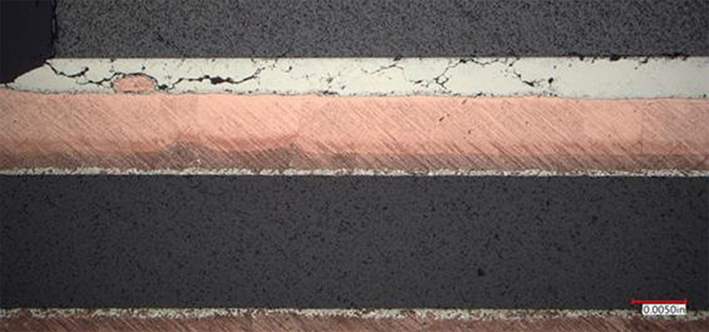
Traditional silicon modules typically exhibit well-characterized failure modes including wire bond lift-off due to thermomechanical fatigue, solder joint cracking from differential thermal expansion, and aluminum metallization reconstruction under sustained thermal cycling (see Figure 4 and Figure 5).
SiC devices introduce unique challenges related to their superior material properties. The higher elastic (Young) modulus and thermal conductivity of silicon carbide, while enabling superior electrical performance, significantly amplify mechanical stress within conventional packaging structures. The increased thermal conductivity creates steeper temperature gradients, while the higher modulus translates thermal expansion mismatches into greater mechanical forces at material interfaces. Consequently, SiC devices in a traditional packaging architecture often demonstrate reduced power cycling lifetime compared to silicon equivalents.
Advanced packaging technologies developed specifically for SiC applications aim to mitigate these challenges through material and structural innovations. Copper clip interconnects replace traditional wire bonds, offering lower resistance paths and improved thermomechanical stability. Silver sintering substitutes for conventional soldering, providing superior thermal and electrical conductivity while exhibiting enhanced reliability under thermal cycling. Active Metal Brazing (AMB) substrates replace Direct Bonded Copper (DBC) alternatives, offering improved thermal expansion matching.
However, these advanced packaging approaches introduce their own potential failure modes. Sintered interfaces, while more robust than solder joints, can experience gradual degradation through void formation and silver migration. Copper clips may fail through fatigue at bond interfaces or through stress concentration at geometric transitions. The complexity of these advanced packages creates multiple potential failure paths that require comprehensive characterization through power cycling analysis.

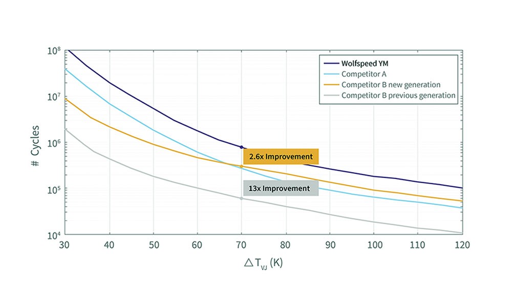
Wolfspeed’s YM4 power module family features copper clip technology, sintered die-attach, and epoxy encapsulation enabling 3 times more power cycles than the best-in-class competitor device in the same footprint (Figure 6).
Testing Methodology and Measurement
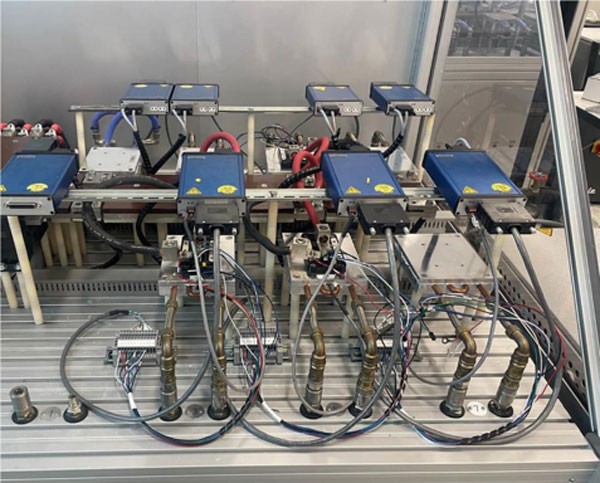
Wolfspeed's power cycling methodology follows standardized protocols while incorporating unique refinements that enhance test accuracy and relevance to real-world applications. The testing infrastructure utilizes commercial power cycling equipment capable of simultaneous module testing (Figure 7), enabling efficient data collection while maintaining statistical rigor through simultaneous measurement of multiple devices under identical stress conditions.
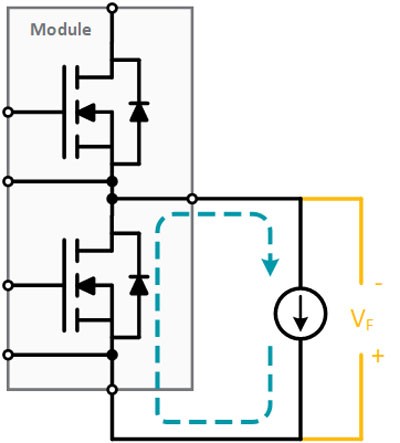
The die’s junction temperature measurement represents a critical aspect of the methodology, requiring high accuracy and fast response time. This operation is usually accomplished using the body diode forward voltage (VF) according to the schematic shown in Figure 8.
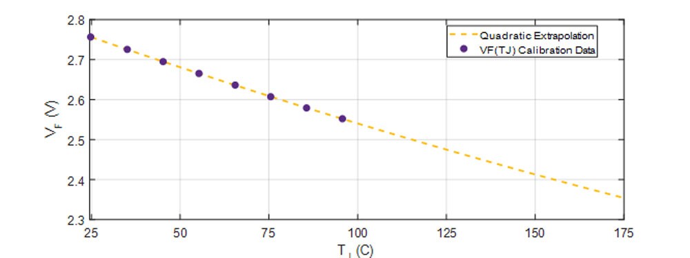
The process begins with performing the temperature calibration, required to determine the relationship between VF and TJ. The process begins by flowing coolant at various temperatures while measuring the body diode forward voltage or each temperature point.
This generates a series of calibration curves that characterize the voltage-temperature relationship. These curves are then mathematically fitted using a polynomial function (Figure 9).
Once the calibration curve has been determined, the test cycle follows the following steps.
- The device is turned on and a constant current is applied through the channel for the duration of ton. Channel current is preferred because it offers better control and more accurately represents real-world application conditions. During the ON state VDS is used as a failure criteria mode.
- The device is turned off and a constant sensing current is applied through the body diode for the duration of toff. The body diode is used during this phase because its forward voltage exhibits high temperature sensitivity and can be measured at low current levels, avoiding unwanted power dissipation. During the OFF state the VF, in case of body diode sensing, is measured as indication of the junction temperature, and is analyzed to calculate RTH, which serves as an additional lifetime parameter under the same standard.
- The previous on-off cycles are repeated continuously, and the test is extended until failure.
Figure 10 shows the VDS and RTH curves over cycles obtained by applying the PCsec testing. Note how the two failure criteria are applied. The first failure criterion, representing the drain-source voltage value at which the failure occurs, corresponds to a 5% increase in VDS from initial values. The thermal failure criterion, instead, corresponds to a 20% increase in RTH (not yet reached in the proposed use case). The vertical increase of VDS on the graph is due to wire bond failures.
Building Life Models
Life model construction begins with test matrix design, requiring careful selection of stress conditions (ΔT, Tjmax and ton) that balance test duration constraints with model accuracy requirements. Higher stress levels accelerate failure mechanisms, enabling reasonable test completion times, but excessive acceleration may activate non-representative failure modes.
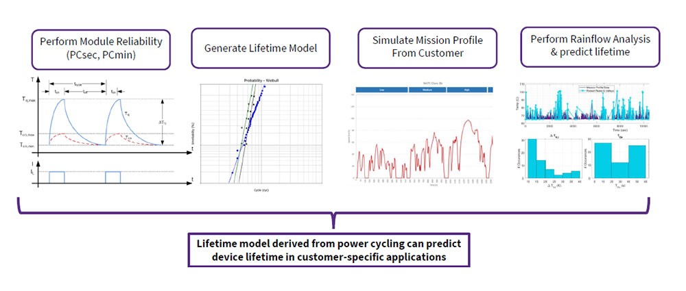
Model application to mission profiles requires sophisticated analysis of actual operating conditions. Customer load profiles are decomposed into thermal cycles through electro-thermal simulation, generating time-series junction temperature data. Rainflow cycle counting algorithms extract equivalent thermal cycles from these complex waveforms, enabling life model application through cumulative damage calculations. The resulting analysis (Figure 11) provides quantitative lifetime predictions for specific operating scenarios.
The Wolfspeed WolfPACK™ module family uses press-fit technology and is best fitted for cost-sensitive applications requiring moderate power cycling capability. These modules eliminate traditional baseplates, utilizing press-fit terminals for electrical connection and simplified thermal management. This innovative approach eliminates the need for traditional solder joints, resulting in mitigating risk of solder fatigue. Its proprietary die solder technique and wire bond design enable industry-leading performance ahead of other available alternatives.
The YM portfolio represents Wolfspeed's automotive-grade six-pack solution, incorporating advanced packaging technologies specifically designed for extreme high-reliability applications. These modules feature copper clip interconnects replacing traditional wire bonds, providing superior current carrying capacity and enhanced thermomechanical reliability. The die attach utilizes silver sintering technology, offering improved thermal and electrical performance compared to conventional soldering while demonstrating superior resistance to thermal cycling degradation. Active Metal Brazing (AMB) substrates provide optimized thermal expansion matching, further enhancing reliability.
Single-switch overmolded modules (TM family) offer a compact packaging solution combining high reliability with reduced form factor requirements. These modules incorporate many of the same advanced technologies as YM modules, including copper clip interconnects and sintered die attach, but utilize overmold compounds for environmental protection rather than traditional housing approaches. This packaging strategy enables integration into space-constrained applications while maintaining automotive-grade reliability performance. The overmold approach also facilitates surface-mount assembly processes, enabling design flexibility in the industry-standard footprint.
Comparative power cycling results illustrate the dramatic impact of packaging technology on application lifetime. Testing under identical stress conditions reveals that epoxy-encapsulated Wolfpack modules achieve significant improvements over silicone gel encapsulated equivalents, while advanced packaging approaches in YM and overmolded products extend lifetimes by orders of magnitude compared to conventional packaging technologies. These improvements directly translate to reduced maintenance requirements, extended system lifetimes, and lower total cost of ownership for end users.
Learn more about how Wolfspeed is advancing packaging technology for silicon carbide.
Predictive Durability
The practical implementation of power cycling analysis extends far beyond laboratory characterization, providing system designers with quantitative tools for optimizing application’s lifetime, predicting maintenance requirements, and minimizing total cost of ownership. Wolfspeed's comprehensive approach encompasses both standardized analyses- and mission-profile simulations.
A reliability analysis begins with detailed mission profile characterization, including operating condition data like load cycles, ambient temperature variations, and duty cycle patterns. By performing electro-thermal simulations it is possible to translate these operating conditions into junction temperature profiles, accounting for thermal dynamics within both the power module and the complete system thermal management architecture. Advanced rainflow counting algorithms decompose complex thermal waveforms into equivalent power cycling conditions, enabling direct application of laboratory-derived life models.
The resulting durability predictions enable predictive maintenance strategies that optimize system availability while minimizing maintenance costs. Rather than relying on conservative time-based replacement schedules, customers can implement condition-based maintenance programs that account for actual operating history and predicted remaining useful life. This approach proves particularly valuable in applications where downtime costs far exceed module replacement costs, such as renewable energy installations or industrial automation systems.
Design optimization represents another significant value proposition, where power cycling analysis guides system architecture decisions to maximize durability. Strategies include thermal management enhancement to reduce ΔTj, module paralleling to distribute thermal stress, and operating parameter optimization to minimize cumulative damage. These design modifications often achieve substantial lifetime improvements with minimal cost impact, fundamentally altering the economics of system ownership.
Conclusion
Power cycling analysis addresses the fundamental challenges of application’s useful lifetime in demanding environments. The evolution from traditional reliability testing to sophisticated durability modeling reflects the increased expectations placed on power electronics as they become integral to critical infrastructure across automotive, renewable energy, and industrial sectors.
Wolfspeed's integrated approach, combining advanced packaging technologies, rigorous testing methodologies, and predictive modeling capabilities, delivers quantifiable improvements in system durability and reliability. The company's portfolio demonstrates how targeted packaging innovations can achieve order-of-magnitude improvements in power cycling lifetime while enabling cost-effective solutions for diverse market segments.