Wolfspeed SpeedFit 2.0 Design SimulatorTM is a fast and useful simulation tool that helps the user in designing optimally for their application by quickly comparing different system specifications, topologies, devices and even thermal parameters. It is a user-friendly tool that can be used to estimate the losses, thermal behavior and efficiency of a system and observe important voltage and current waveforms. SpeedFit’s features are discussed in more detail here.
SpeedFit 2.0 allows the user to simulate six different single-phase topologies for AC/DC applications (Figure 1). These topologies are active, single-phase boost mode circuits, used for Power Factor Correction (PFC) applications (Figure 2). Designs for PFCs are driven based on low cost and high efficiency. Standards such as 80 PLUS® for efficiency requirements of power supplies and IEEE 519 for harmonic content of power supplies keep getting more stringent. To be compliant with today’s efficiency standards, it is required for power supplies to have a highly efficient PFC stage. SpeedFit Simulator provides the capability to evaluate designs using SiC devices for high frequency operation, and configurable Si or SiC diodes for low frequency operation to assist the user in designing their PFC.
Figure 1: SpeedFit - Application Tab
Figure 2: SpeedFit - Input Tab
This article focuses on highlighting how SpeedFit can help in comparing different topologies and assist in designing the most efficient converter using AC/DC applications as example. As an illustration, we compared three different topologies assuming a set of system specifications. These specifications are chosen based on Wolfspeed 3.6 kW Totem-Pole Converter Reference Design. The performance of these topologies for the chosen specifications are presented and compared. These topologies are: Classical Boost Converter, Totem-Pole Converter – LF Diodes, Totem-Pole Converter – LF MOSFETs.
Parameter
Value
Input Voltage
230 V (RMS) – Nominal
Voltage
420 V (DC)
Output Power
3.6 kW – Max
Line Frequency
50 - 60 Hz
Switching Frequency
60 kHz
Inductor Value
0.44 mH
Deadtime
200 ns
Table 1: Specifications from the 3.6 kW Totem-Pole PFC reference design
SpeedFit Parameters
The specifications from Table 1 can be entered in the different tabs in SpeedFit. More information related to the different tabs on SpeedFit is available here. The information given in Table 2 can be used to specify parameters in alignment with the 3.6 kW Totem-Pole Converter reference design.
Tab
Parameter
Value
Input
Input Voltage
230 V
Input
Output Voltage
420 V
Input
Related output power, So
3600 VA
Input
AC Frequency, Fac
60 Hz
Input
Switching Frequency
60 kHz
Input
Deadtime
200 ns
Device
Number of parallel MOSFETs
1
Device
Turn-on gate resistor, Rg-on,ext
4.7 Ohm
Device
Turn-off gate resistor, Rg-off,ext
2.2 Ohm
Thermal
Thermal interface resistance, Rth,ch
0.985 K/W
Thermal
Heatsink temperature, Th
Variable
Thermal
Thermal resistance, Rth,ha
1.7 K/W
Thermal
Heatsink time constant, τha
60
Thermal
Additional heat source on heatsink, Padd
0
Thermal
Ambient temperature, Tamb
50 oC
Simulation
Inductor, L
0.44 mH
Simulation
Silicon Diode Forward Voltage, Vf
0.92 V
Simulation
Silicon Diode On-Resistance, Ron
0.033 Ohms
Table 2: SpeedFit parameters and their values
The thermal parameters are in alignment with the 3.6 kW Totem-Pole reference design. The thermal interface resistance, Rth,ch = Rth, + Rth,PCB + Rth,TIM = (0.015 + 0.45 + 0.52) K/W = 0.985 K/W.
The heat sink to ambient thermal resistance is 3.4 K/W given in the reference design. However, this applicable to a heatsink for a half-bridge leg. Since we have two such legs, the affective heat sink resistance can be approximated to 1.7 K/W. Therefore, Rth,ha = (3.4 / 2) K/W = 1.7 K/W.
In the Simulation tab (Figure 3), the forward voltage drop (Vf) and on-resistance (Ron) parameters are provided to include the losses in the rectifier diodes for the efficiency calculations. The user can edit these values based on the rectifier diode they intend to use. These diodes can be Si or SiC diodes. Since these diodes will be operating on low frequency waveforms, they contribute significantly only to the conduction losses. The losses in such devices are shown in the ‘Device Overview’ table.
Figure 3: SpeedFit - Simulation Tab
The Summary tab shows a system overview of losses and waveforms. Specifically, for the AC/DC topologies, the rectifier diode losses and LF MOSFETs fields are also included.
Topology Comparison
For illustration in this article, three different PFC topologies are compared. This section contains important notes and observations about these topologies and focuses on how SpeedFit can assist in comparing these different topologies.
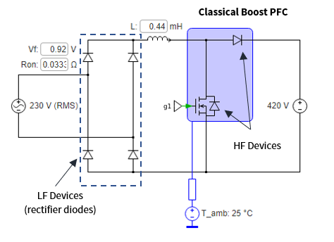
Classical Boost PFC
Figure 4: Classical Boost PFC Topology
The Classical Boost topology is comprised of a full-wave rectifier tied to a boost converter. The rectifier diodes do not see the switching frequency; therefore, Si rectifier diodes can be used for this the rectification stage. However, the current passing through the rectification stage adds only to the conduction losses in the converter. Therefore, the Vf and Ron parameters are sufficient to define the losses in these diodes. It can be observed from Figure 6, the rectifier diodes are the least efficient devices, impacting the total efficiency of this topology. Therefore, it is crucial to observe the losses in all the components of a system while evaluating efficiency of a topology. Owing to its lower efficiency, Classical Boost PFCs are appropriate for low-power applications. This topology is appropriate to comply with Silver or Gold 80 Plus Standards.
In SpeedFit, the rectifier diodes are configurable by the user in terms of forward voltage and on-resistance: i.e. Vf and Ron. The ‘Device Overview’ table shown in Figure 6 shows the distribution of losses in the different devices – MOSFET, Diode (boost stage) and rectifier diodes (rectification stage).
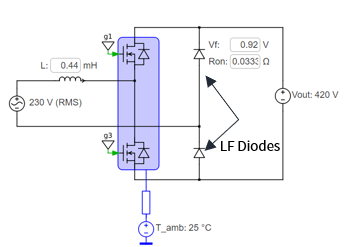
The Totem-Pole Converter with Low Frequency (LF) Diodes is comprised of two MOSFETs operating at the switching frequency and two diodes which see the line frequency waveforms. The users can choose Wolfspeed MOSFETs from the device tab and can configure their diodes based on specifications such as forward voltage (Vf) and Ron (On-resistance) of the Si or SiC diodes they intend to use. It is a cost-effective topology with least number of components. It is an improvement over the classical boost PFC since it eliminates the line-frequency rectifier, but slightly less efficient than the Totem-Pole Converter with LF MOSFETs due to higher conduction losses in the rectifier leg.
The Totem-Pole converter with Low Frequency (LF) MOSFETs employs two High Frequency MOSFETs and two Low Frequency (LF) MOSFETs. This topology does not use any rectifier diodes. The conduction losses incurred in the LF MOSFETs are significantly lower compared to rectifier diodes. Therefore, this is the most efficient topology. However, more gate drivers required here can add to the size and cost of the converter.
Summary
Table 3 summarizes the details of the three topologies in consideration. The devices used are listed in this table and a comparison of the efficiencies is made.
Table 3: Comparison between the three topologies: Classical Boost, Totem-Pole Converter- LF Diodes, Totem-PoleConverter- LF Mosfets
Note: The peak efficiency (>99%) stated in the reference design for the Totem-Pole Converter – LF MOSFETs includes the losses in the auxiliary power supply and other components of the converter, whereas the efficiency stated above only includes the losses in the power semiconductors.
SpeedFit Simulator 2.0 allows the user to compare different topologies and designs for their applications. It provides the user flexibility to select the optimal SiC MOSFETs and SiC Schottky diodes, and to configure the specifications of low-frequency silicon diodes to help estimate a realistic value of the efficiency of the converter. The System and Device Overview tables, as shown in Figures 6 - 8, on the Simulation tab summarize the losses in the different components like HF MOSFETs, LF MOSFETs, and SiC/Si Rectifier Diodes to conveniently analyze the losses in each device separately and optimize the design.
See how Wolfspeed LTspice models can make designing with silicon carbide in power electronics systems more efficient, cost-effective, and accurate. Get started optimizing your system design, without the need for physical samples or test kits.
The design and geometry of power modules enable EMI modeling which empowers designers to predict and understand their system’s EMI behavior early in the design process.
Join Wolfspeed Applications Engineer Chris New as he unboxes the 25 kW three-phase inverter reference design and demonstrates how to get started evaluating power electronic system performance right out of the box.