The industry's lowest on-state resistances and switching losses for maximum efficiency and power density
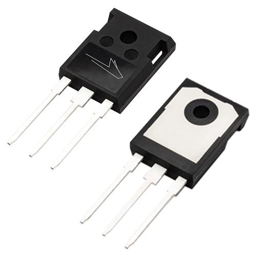
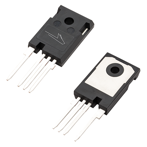
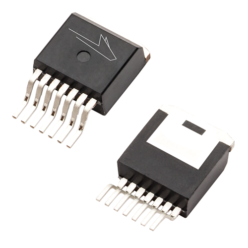
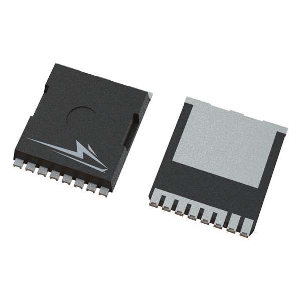
Wolfspeed extends its silicon carbide (SiC) technology leadership with the introduction of 3rd-Generation 650 V MOSFETs, enabling smaller, lighter, and highly-efficient power conversion in an even wider range of power systems. The 650 V MOSFET product family is ideal for applications including high performance industrial power supplies, server/telecom power, electric vehicle charging systems, energy storage systems, uninterruptible power supplies, battery management systems, and other applications.